What is Total Harmonic Distortion (THD)?
In signal processing, total harmonic distortion (THD) is an essential term, especially when examining the electrical power quality or audio signal fidelity. Fundamentally, THD measures how much undesired harmonic frequency is introduced into a periodic waveform, such as an audio or electrical signal, causing it to diverge from its ideal sinusoidal shape. Various factors, including power supply problems, non-linearities in electrical components, and flaws in audio gear, may cause these harmonics, which are multiples of the waveform’s fundamental frequency.
 Fig 1: A sinusoidal voltage signal in the time domain
 Fig 2: A square wave voltage signal in the time domain
To understand the concept of harmonics, we usually consider sinusoidal waves because a square wave combines different sinusoidal waveforms with varying frequencies and definite RMS values. However, Sinusoidal waves, along with square waves in the time domain, have zero distortion in their pure form, as shown in Figure 1 and Figure 2.
Why is There a Need to Calculate THD?
In order to evaluate signal quality, detect system problems, guarantee compliance to various standards, optimize system design, avoid equipment damage, and increase efficiency in a variety of applications, it is necessary to calculate total harmonic distortion or THD. THD measurement gives engineers useful information about a waveform’s quality, enabling them to assess the integrity and fidelity of the signal. High THD values indicate significant harmonic distortion, which may deteriorate signal quality, impair system functionality, and cause equipment damage. Engineers may find causes of distortion, diagnose problems with the system, and take remedial action to enhance performance and reliability by keeping an eye on THD levels.
THD Calculation
THD calculation involves several steps.
-
Obtain the Fundamental Frequency
The waveform’s fundamental frequency must be located and isolated as the initial step. This is the signal’s principal oscillation and its lowest frequency component.

-
Identify Harmonic Frequencies
Harmonic frequencies are integer multiples of the fundamental frequency, which helps identify them. These undesirable frequencies distort the original waveform. The second harmonic (2 times the fundamental), the third harmonic (3 times the fundamental), and so on are examples of common harmonics.
Equation: F harmonic = n×F fundamental , where n = Integer representing the harmonic number
Here, we show harmonics for sinusoidal and square waves to explain the concept.
 Fig 3: A sinusoidal voltage and a square wave, with the square wave having peaks at the harmonic frequencies.
Here, we generated two waves: a square wave and a sinusoidal wave, and we used the Fast Fourier Transform (FFT) to calculate the corresponding frequency domain representations of both. Because it is discontinuous, the square wave shows peaks at the harmonic frequencies, while the sinusoidal wave mostly shows energy at its fundamental frequency. These peaks at harmonic frequencies influence Total Harmonic Distortion (THD), which measures the harmonic content relative to the fundamental frequency. The figures tell us that as you take the Fourier transform (changing them into frequency domain) of the sinusoidal wave and the square wave, the former one will have only one beep, and the latter one will have multiple beeps in its audio, depicting that it has peaks at different harmonic frequencies.
Measure RMS Values
To compute THD, we find the RMS values of the fundamental frequency and each of the harmonic frequencies independently, representing the waveform’s effective amplitude.
Equations for RMS Voltage VRMS of a waveform is categorized below:
For Discrete samples:

For Continuous samples:

Vrms=21T 0T(vt)2 dt
- vi = Instantaneous voltage value at sample i
- N= Total number of samples
- v(t)= Instantaneous voltage as a function of time
- T= Total duration of the signal
Square and Sum
Square each of the RMS values that were found in the previous step and add them all together except for the fundamental harmonic. The entire power of all harmonic frequencies, excluding fundamental harmonic, is represented by this sum.
The equation will be:
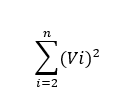
Where Vi= RMS Voltage of the ith harmonic frequency.
To compute THD, divide the RMS value of the fundamental frequency by the square root of the sum that was produced in step 4. Next, multiply the result by 100 to get the THD percentage.

- We know THD as the total harmonic distortion, represented as a percentage.
- The RMS voltage of the fundamental frequency is denoted by V1.
- We denote the total number of harmonics used in the computation as “n.”
High level of Total Harmonic Distortion (THD)
High harmonic distortion in a waveform relative to its fundamental frequency is indicated by high Total Harmonic Distortion (THD) values. This results in low-quality audio systems’ signals, which produce distortion and interference that may be heard.
Low level of Total Harmonic Distortion (THD):
When a waveform’s total harmonic distortion (THD) is low relative to its fundamental frequency, it means that there is little distortion present. This guarantees consistent power quality in electrical systems, good signal fidelity in audio systems, and effective equipment functioning. Achieving clear and artifact-free audio reproduction requires minimal THD.
Measurement of Total Harmonic Distortion (THD)
- Here, we use a sinusoidal wave input signal with a fundamental frequency of 5 Hz as a baseline for any further examination.
- Then, we find its harmonic elements that are present in addition to the base frequency. These harmonics (10Hz, 15Hz, 20Hz, 25Hz) appear as integer multiples of the fundamental frequency. Distortion could be random as well. In this example, we choose a periodic but non-sinusoidal harmonic.
- To calculate Total Harmonic Distortion (THD), divide the root mean square (RMS) voltage of the fundamental frequency by the root mean square (RMS) voltage of the harmonic components. THD is a percentage that indicates how much a wave deviates from a pure sine wave.
 Fig 4: THD Depiction
In order to calculate the extent of distortion, we use a Harmonic Distortion Analyzer. Let’s move forward towards Harmonic Distortion Analyzer.
Harmonic Distortion Analyzer
A harmonic distortion analyzer measures the degree of harmonic distortion in a waveform by comparing it to an ideal sinusoidal waveform. Generally, it calculates the Total Harmonic Distortion (THD), which is the amplitude of harmonic frequencies in relation to the fundamental frequency. In applications like audio engineering, telecommunications, and power systems, where high fidelity is crucial, it offers insightful information about the signal’s quality and integrity.
 Fig 5: Harmonic Distortion Analyzer
Components of Harmonic Distortion Analyzer
Input Stage:
To interact with the signal source, a harmonic distortion analyzer’s input stage is furnished with connectors or input jacks. Handling different signals of different types and intensities could include functions like filtering, attenuation, and input impedance selection.
Signal Processing:
The analyzer’s signal processing circuitry analyzes the incoming signal, separates its harmonic components, and determines the overall harmonic distortion. The processing may include some common filters.
These filters work to reduce unwanted noise or interference and extract certain frequency components. Harmonic distortion analyzers often use the following sorts of filters:
- Bandpass filters attenuate frequencies outside of the specified band while allowing just a certain range of frequencies—corresponding to the harmonics of interest—to pass through. In order to separate individual harmonics from the input signal, bandpass filters are necessary.
- Also referred to as band-stop or reject filters, notch filters enable frequencies outside of a certain range to pass through while attenuating frequencies within the range. When suppressing certain harmonic frequencies or blocking sounds that might obscure the intended harmonics, notch filters come in handy.
- Moreover, Low-pass filters let lower frequencies go through without modification while attenuating frequencies over a predetermined cutoff frequency. Users employ these filters to remove undesirable higher-order harmonics and high-frequency noise that might skew the analysis.
- On the other hand, high-pass filters offer passage for higher frequencies while attenuating frequencies below a certain cutoff frequency. They use them to guarantee precise identification of higher-order harmonics by eliminating low-frequency interference or noise.
- Designers create comb filters to selectively attenuate or boost frequencies at regular intervals. In harmonic distortion analysis, analysts may utilize comb filters to suppress some harmonic frequencies and isolate and highlight others.
Display and Controls:
THD measurements and waveform graphical representations are among the visual feedback of the distortion analysis findings that are provided by the display panel. Users are able to change settings, choose measurement parameters, and analyze the results via control knobs, buttons, and menus.
Data Output:
A few harmonic distortion analyzers provide built-in storage for storing and exporting measurement data, digital interfaces (USB, Ethernet), and analog outputs (voltage or current).
Operation of Harmonic Distortion Analyzer:
The signal of interest is linked to the analyzer’s input in order to evaluate harmonic distortion using a harmonic distortion analyzer. After processing the signal, the analyzer determines the THD level and separates the harmonic components. To customize the study to their own needs, users may change parameters like measurement mode, bandwidth, and frequency range. Usually, the analyzer’s screen or output interface displays the findings for interpretation.
Applications of Harmonic Distortion Analyzer
Audio engineering: To ensure high-quality sound reproduction, harmonic distortion analyzers are used to evaluate the fidelity of audio equipment, including speakers, amplifiers, and recording devices.
Power Systems: Harmonic distortion analyzers are used in power systems to monitor and evaluate the quality of electrical power, pinpoint distortion sources, and determine whether or not regulations are being followed.
Telecommunications: Technicians use these analyzers to assess signal integrity, reduce distortion, and maximize transmission performance when testing telecom equipment.
In conclusion, understanding THD, or Total Harmonic Distortion, is a crucial metric for evaluating signal quality in audio and electrical systems. Elevated Total Harmonic Distortion (THD) levels indicate noteworthy harmonic distortion, which may result in reduced signal quality, interference, and even device failure. Conversely, low THD levels indicate little distortion, which leads to a consistent power supply, effective equipment functioning, and crisp, high-quality audio reproduction. In order to measure and evaluate THD and provide insightful information for troubleshooting, optimization, and quality assurance in a variety of sectors, harmonic distortion analyzers are essential. These tools support the identification of distortion sources, the assessment of signal integrity, and the assurance of regulatory compliance. Professionals may maximize system performance, reduce energy losses, and improve dependability by using harmonic distortion analyzers.

Fatima Razzaq is a freelance technical writer who served as an electrical engineering lecturer at Air University—a federally chartered public sector research university in Pakistan. Razzaq holds a Bachelor’s degree with distinction in electronic engineering from Ghulam Ishaq Khan Institute of Engineering Sciences and Technology (GIKI) and a Master’s degree in Sustainable Transportation and Electrical Power Systems from the University of Nottingham, Universidad de Oviedo, and La Sapienza University of Rome. Razzaq’s diverse work experiences in academia and industry continue to inform her prolific technical writing journey in the areas of electrical engineering, storage mechanisms, power electronics, electric vehicles, energy, and related topics.